[You can find other DIY photography projects
here]
[Also I'd like to shout out to the good folks at Photojojo - if you like photo goodies, I'd recommend perusing their
catalog of awesome.
*]
Fisheye lenses are insanely fun to shoot with. They allow you to shoot at very wide angles - wide enough lenses will get people standing
right next to you into the shot. I've always loved the
wide angle look in videos, and I thought it'd be an awesome exercise in redundant and needless hackery to build my own.
Here's the gloriously ugly result:
Built using a fisheye peephole as the main lens element and a decapitated soda can as the lens body (!), this attaches directly to my SLR camera. For well under US$20, I ended up with a lens that has nearly a 180-degree field-of-view, adjustable focus, a canon EOS mount, and due to it's stylish and sleek exterior, can generate limitless amounts of
admiration ridicule confusion. Unlike commonly (and cheaply) available
fisheye adapters, this build does not attach to the front of an existing lens - it's a completely self-contained unit that doesn't require any other optics to work.
Step 1: Research!
The cheapest and easiest to get fisheye lens out there at the moment is the garden variety door peephole lens. These simple optical devices can be picked up
cheaply at your local hardware store. I picked up mine for US$6; it offered a huge field of view (nearly 180 degrees).
As I discovered in my
previous hacks, individual lenses are hard to directly transplant from one device to another. Often an intermediate lens is required to refocus the image so it hits the sensor/film correctly. The peephole lens couldn't be used directly with the SLR - like the
phone-o-scope, it needed a
teleconverter is needed to magnify the small image at the end of the fisheye barrel, and bring it into focus at the image sensor.
A number of
good tutorials have gone over the method of using an existing, standard lens as a teleconverter. That's where I started:
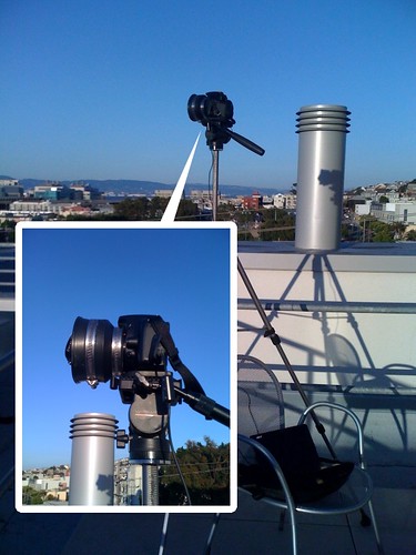
 First attempt
...and while this works, I didn't like the idea of having a complex lens in-between the fisheye and the camera. Modern lenses have many internal elements, each one dimming the image coming from the fisheye and leading to low-contrast images. I wanted to build a lens that would remove the complex in-between lens and replace it with a simple one that wouldn't lose quite as much light.
Step 2: Testing
I needed to couple the fisheye lens with something that would magnify the image coming out of it, and space it so that it would form a good image at the sensor. Rummaging around in my parts box, I found an old, single element projector lens that came from an old 35mm slide projector. These are pretty
pretty easy to find, and I've seen them a lot at garage sales.
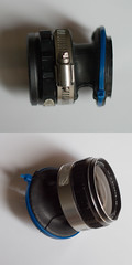
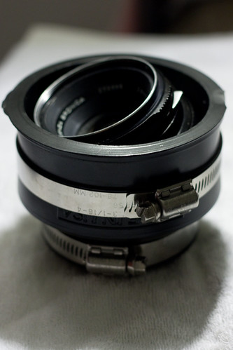
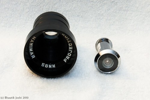 Left: projector lens, right: fisheye lens
I took the body cap off my camera, and held the two lenses in front of the body. Looking through the viewfinder and experimenting with the lens positions, I was able to come up with an estimate for how far the lenses needed to be apart from each other and the camera body to make a reasonable image. Running around loosely holding lenses in front of the camera tends to be fraught with danger, however, so the next step was to build a permanent enclosure for them.
Step 3: Design
The materials list for the design:
- Projector lens (US$3, second-hand)
- Door peephole lens (US$6, new from the hardware store)
- T-mount to EOS adapter (US$9 new from eBay, but you can use a drilled out body cap instead which would be ~US$4)
- Soda can (US$1)
- Packing foam (US$0)
- Cardboard stopper rings (US$0)
- Plumbing clip (US$0.5)
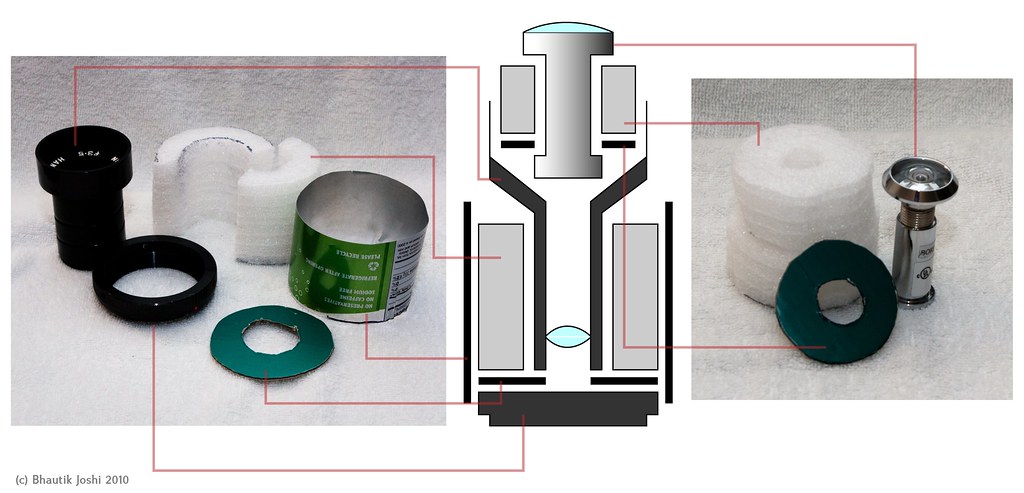 The design centres around having two main components - a lower enclosure for holding the projector lens, and an upper slot for the fisheye lens.
In the design, the lens attaches to the camera using a T-mount to EOS adapter. It turns out that the adapter I was using had nearly exactly the same diameter as a soda can, so I decided to use that as my lens body. To hold the projector lens firmly in place in the can, I made use of two pieces of packing foam, cut into halves of a cylindrical tube that fit around the projector lens. Since the foam I was using is not completely opaque, I also inserted a cardboard ring cut into the shape of a donut at the base of the foam cylinder to stop light leaks.
A similar principle is used to fit the fisheye lens into the projector lens mouth. Foam discs that are a little larger than the diameter of the projector lens mouth are cut out; in the centre of this a hole is made so that the fisheye lens fits snugly inside them. Another cardboard stopper is placed at the base of the foam to stop light leaks.
Step 4: Building the tin cam
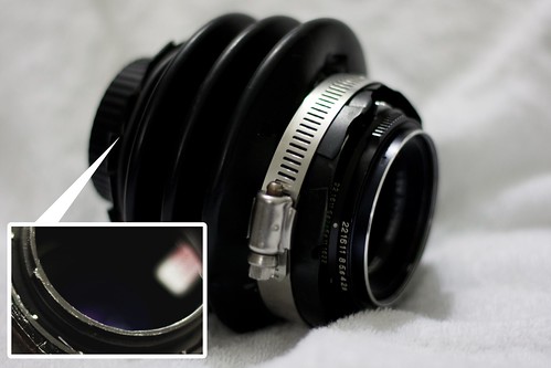
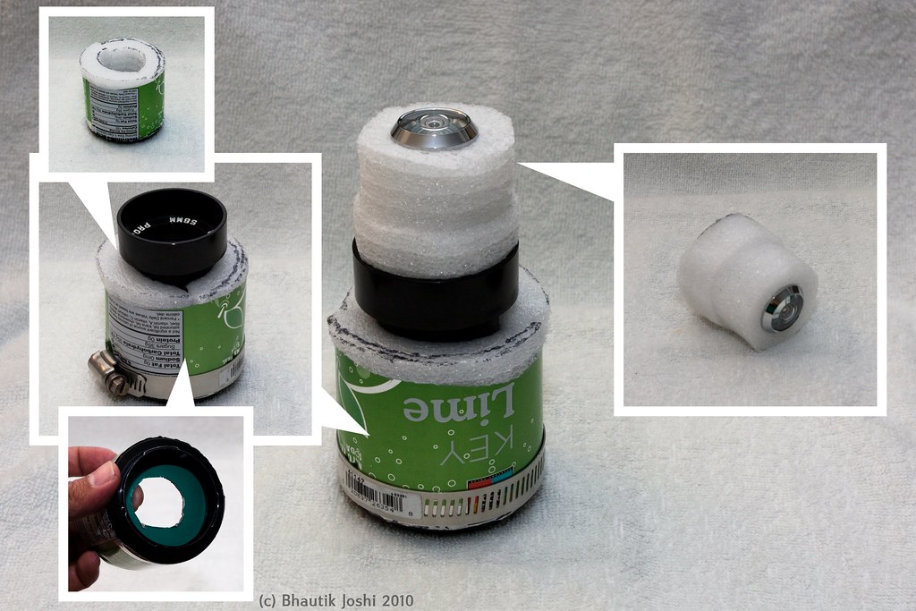 Actual assembly
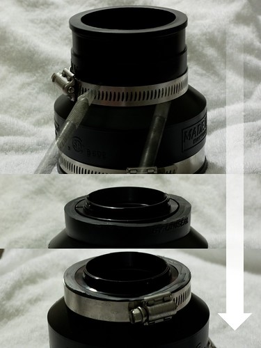
Assembly was pretty straightforward. The t-mount is inserted into the can first, and the stopper ring on top of it. The foam cylinder halves are inserted next. To keep things extra secure, a plumbing clip is wrapped around the mount end of the can. The projector lens was carefully inserted into the centre of the foam cylinder tube. The projector lens that I had has a screw-thread, so I was able easily twist it into place. This added an extra bonus - turning the projector lens unscrews it, allowing for racking the lens back and forth - which means that the lens can be adjusted for focus.
Most door fisheye lenses come in two parts - a lower part which goes into the back of the door, and an upper part which screws into it from the front side of the door. Separating the lens into these two halves, the cardboard stopper is slid it on to the lower half. The foam discs are slid on next, and then the top half of the fisheye is screwed back in. This whole assembly is snugly fitted into the mouth of the projector lens, and then the build is complete!
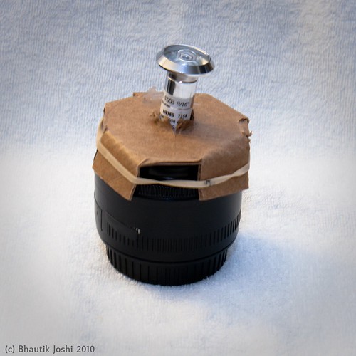
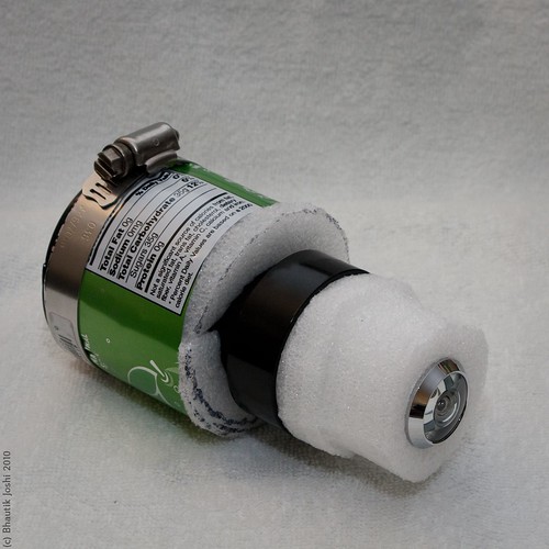 Final build
Even if your projector lens doesn't have a thread, you can still adjust the focus by turning the upper half of the fisheye lens - unscrewing it a little with lengthen the lens body, allowing you to finely focus it.
Step 5: Going nuts
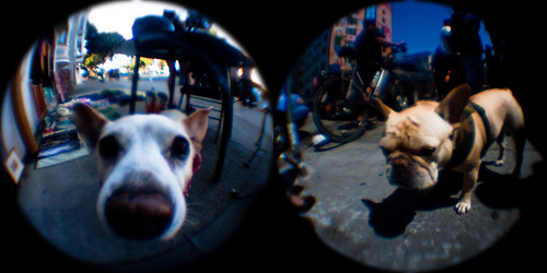 woof!
woof!The fisheye lens is ludicrously fun to shoot with. If you can, get in close to your subject - you'll be surprised how close you can get and still have your surroundings in the frame. Pets are always awesome for fisheye photos, especially if they're happy to stick their nose into the lens.
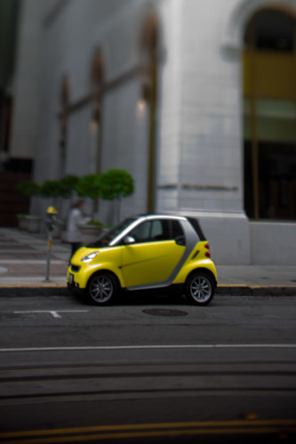
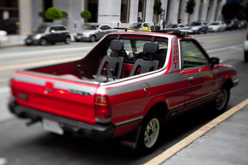
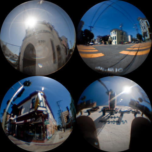 Mission District
The lens combination makes saturated, contrasty pictures. As the results show, door fisheye lenses were never meant for even vaguely serious photography, and individual images don't stand up well to close inspection. In future revisions I think I might experiment with adding in an aperture to crank up the f-stop and perhaps reduce some of the sharpness and colour artefacts.
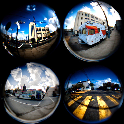
However, if you take a few of the fisheye pictures and arrange them into a grid, you can use them to tell a story or paint a picture of a place with a few images. In all of these shots I've cropped the images to squares, and then used a circle mask to get a clean circular crop around the edges of the pictures.
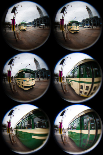
 Potrero Hill Portraits
Go nuts with it, and get in close - I don't think you'll be disappointed :) You can find other fisheye tin-cam photos on flickr
here.
 fffffff-isheye!
I keep this site free-as-in-beer, but shopping on the photojojo site via
this link contributes in a small way to my needless-optics-gear-fund and makes for a very happy photo nerd.