11 September 2009

Why I ride a bike

Route 1: Getting the 22 MUNI bus back home from work


Distance: 6.7km
Time: 45 mins (not including time to walk to the bus stop!)
Average speed: 9km/h (!!)
Pros: Not driving, can read a book
Cons: Getting stabbed in the pancreas, the malefic odour of a San Francisco transient as they sit right next to you

Route 2: Riding my bike


Distance: 11.0km
Time: 37 minutes
Average speed: 18 km/h
Pros: Exercise, the view along the waterfront, not being tied to a bus schedule
Cons: Headphone-wearing pedestrians walking out in front of you, splashback from the giant octopus that occasionally tries to destroy the Golden Gate Bridge

7 September 2009

Bay Bridge Bypass

[Prefix: A huge, enormous thanks has to go out to Margena Wade, (Community Liaison Officer) and other staff at the Bay Bridge project at Caltrans for giving me the opportunity to go out and look at the construction of the bridge. It's an amazing project on an enormous scale, and I've been enormously lucky to have had the opportunity to go out and have a look at it first hand :)]

I set out on Friday afternoon after work to have a look at the Bay Bridge bypass construction work first hand. Heading over on the trusty 108 MUNI, I scuttled about Yerba Buena and Treasure Island trying to get a few good shots. I nabbed a spectacular moonrise over the construction site:

Bay Bridge bypass: Moonrise behind Bay Bridge

...as well as a time-lapse with ye olde plungercam of the old bridge section being rolled out, as well as a timelapse of the moonrise :)


However, I was lucky enough to be invited back to the island for a tour of the site on Saturday evening - and it was absolutely spectacular.

Bay bridge bypass: construction site


This is the boat pier on the East side of the bay bridge construction site. Here a service connected the two Caltrans command centres at Yerba Buena island, and it's from here I got the awesome ferry ride out on the water to have a look at the entire span of the bridge.

On the left hand side of the image you can see the new section of the bridge completely rolled into place; when I arrived on Saturday evening it was being worked on by engineering crews who were working on a pile of verification and connection tasks.

The bypass weighs about 7000 tons (!) and was assembled 50m up in the air and slid into place on rails. I asked about what it takes to overcome that sort of inertia to get it moving, and the answer was lots of hydraulics and dish soap.

In the mid-ground on the right two-thirds of the image, you can see the existing Bay bridge; just behind it is the new bridge. For the majority of the distance, the deck is in a side-by side configuration. I believe that the current point where it is up to is named W2; from there until pier E2 (mostly obscured by the construction work) it becomes a deck suspended by a pylon, and after that it converts into a double deck configuration to enter into Yerba Buena island.

Bay bridge bypass: E2 and W2


On the far left of the image, you can see 'falsework' construction leading up to pier E2; on the right, you can see the twin deck coming over from Oakland and pier W2. The falsework is in place so that the deck, which is normally going to be suspended from a pylon, can be constructed whilst the pylon is put into place. When the suspension cables are added, the falsework will be removed.

Bay bridge bypass: The Left Coast Lifter


The Left Coast Lifter is one of the world's largest floating cranes, and was constructed specifically for the job of installing sections of the Bay Bridge. This behemoth is about 30 stories high (!) and after the job with the Bay Bridge is likely to be deployed elsewhere. Before construction it was used to lift a sunken WW II tugboat. Here you can see it parked at Oakland, just in front of some falsework that is going to be used to temporarily support the span of the new bridge.

Bay bridge bypass: Plungercammed Oakland crane


One of the many characteristic cranes lining the Oakland foreshore.

Bay bridge bypass: Work on the cracked eyebar on the east span of the Bay Bridge


Inspection of the Bay Bridge revealed that a two-inch crack in an eyebar on the East span of the bridge; I'm pretty sure the crane and lift in the middle are near where the broken eyebar is. The crack means that the re-opening of the bridge may need to be delayed whist crews work overnight on fixing the problem.

Bay bridge bypass: East span of the Bay bridge with repair work on the broken eyebar


This is my favourite shot; the plungercam does all sorts of interesting things with smearing out point light sources. Golden hour at sunset is very, very kind to photographers in the Bay area summer :)

In the centre of the image you just make out the crane next to the newly discovered broken eyebar support on the bridge.

All in all, it was an awesome weekend :D The full photoset is here.

11 August 2009

More photon-based shenanigans

Last weekend was a trip up to South Lake Tahoe, and it wouldn't have been the same without some unwarranted and needless geeking out.

I was keen to test both plungercam 2 and the time-lapse recording setup under some more challenging conditions out in the field.

I'm a huge fan of Keith Loutit and his use of tilt-shift for minituarisation, and I wanted to have a go myself:


I carried a netbook, camera, lens and mini-tripod up on the hike around Emerald bay to get the shot. Chuck kindly took a couple of shots of me setting up the whole thing and running the capture, so you can get an idea of how (relatively) minimal the setup is:


On a less terrestrial scale, I also wanted to get a nice capture of stars in motion. Given that we were well outside of the city, I thought it was a a reasonable enough proposition - however, the moon was nearly full, so that did tend to wash things out a fair bit as soon as it rose. However, the result wasn't awful:


I used auto-levels to try to bring out the stars a bit, but it does tend to cause some odd colour artifacts - see the weird green hues in the second sequence above. Next time I think I'll try to control the levels manually rather than leave it to an algorithm.

On the plain old 2D front, Tahoe yielded a few nice shots:

Tahoe Shenanigans 2009: chipmunk!

Tahoe Shenanigans 2009: more little boats!

Full set here.


...and last Wednesday, I was helping out the San Francisco Bay Guardian again by taking some candids at the annual Best of the Bay party downtown. Good time had by all :)

SFBG BOTB 2009 party: DJ Paul Paul

SFBG BOTB 2009 party: J-Boogie's Dubtronic Science

SFBG BOTB 2009 party: Sila and the Afrofunk Experience

SFBG BOTB 2009 party: funking out

Full set here.

27 July 2009

Plungercam 2: cheaper and more predictable :)


New visitors: the updated DIY tilt-shift lens tutorial is here: http://cow.mooh.org/projects/tiltshift.

In it, I've got a comprehensive guide to how tilt-shift works, along with a guide to using existing 35mm lenses to build DIY tilt-shift lenses.


[Edit #0: hi to everyone from hackaday, crunchgear, makezine, lifehacker, and wired! And Photojojo too :)]

[Edit #1: Some new results with Plungercam 2 here; earlier video experiments with tilt-shift here and here.]

[Edit #2: Those who are looking for the reasoning behind the project and details on how to get parts might want to check out the write up for the original plungercam first.]

[Edit #3: Need a tip with building the plungercam? Want to collaborate on a project? Don't hesitate to drop me an email]

[Edit #4: See some of my other DIY projects (plungercam 1, iPhone SLR lens adapter, papercraft etc) here]

Original plungercam with worn out body cap mounting ring

The original plungercam that I built earlier this year has been an absolute joy to use. However, the original design has a couple of problems.

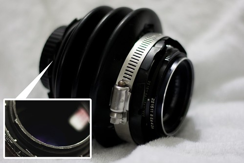
1) The mounting mechanism to attach it to the camera uses a plastic body cap, which was never designed to hold much weight. As a result, the teeth on the cap have been slowly disintegrating under the weight (see inset, above). Mounting the lens has now become pretty unreliable.

2) Usage - there is a lot of fun to be had by forcing the user to tweak the focus by hand, meaning zero repeatability - no two plungercam shots will ever be the same. However, this means that it is unusable for time-lapse video applications, where it is important to keep the lens in the same place between shots.

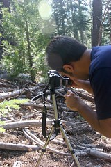
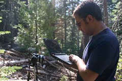
I'll go through the construction of the dead simple Plungercam 2, which addresses the above two issues. It's worth pointing out at this stage that this is the first step in getting the plungercam to behave like a proper tilt-shift lens. Currently it only really handles tilt, so, strictly speaking, it's role is more like a very quirky selective focus mechanism than actual perspective correction.

Plungercam 2: components

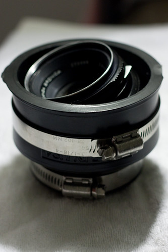
Plungercam 2 keeps in the spirit of the original plungercam by using cheap plumbing equipment and affixing it to precision optics. This iteration eliminates the need for glue altogether, so all the optical components can be easily taken out and re-used elsewhere.

The main component is a rubberized pipe coupling, which I got for $7 at the always awesome Center hardware. The two adjustable steel bands will be used to hold the mount and lens securely in place. This particular one is two inches on the narrow end, and three on the wider end.

To fix the problem with the body cap mount teeth fraying, I decided to replace it with a T-mount T-mount adapter. I picked up the one I'm using for $3 from one of the closing Ritz camera stores.

I'm re using the $12 (from ebay) Zenza bronica medium format lens that was in plungercam 1. Since this was only held in place using a metal clip, it was easy to take it out and re-use it.

Total cost: ~$22 :)

Plungercam 2: Modifying the pipe coupling and adding the t-mount adapter

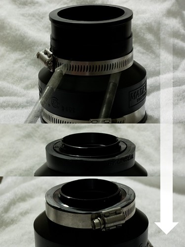
The narrow end of the pipe connector is going to be connected to the camera; to maximise the usability of the lens, we want the narrow end to be as short as is practical. The general idea is to put the t-mount adapter into the narrow end, and to use the pipe clip to secure it into place.

Slide the pipe clip as far along as it can go along the connector, and score using a hobby knife around the edge of it that is going to be attaching to the camera. Remove the clip, and cut along the score line (again, a hobby knife will do the job here) to chop off the top of the connector. Keep the cut as perpendicular to the surface as possible.

My T-mount adapter was a little than two inches on its external diameter, and the connector itself is designed with a two inch fitting on its narrow end. With a bit of careful levering, the adapter can be wedged into the connector. Whilst it is a good fit, it's a good idea to put the pipe clamp back on and screw it tightly into place. Last thing you need is the adapter falling apart when it is on the camera :P

Plungercam 2: final assembly

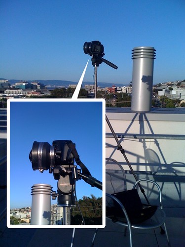
To finish the adapter, place the lens inside the wide end of the connector, and adjust to get the tilt desired. To fix it into place, simply tighten the screw clip. To reposition, loosen the screw clip, mess about with the lens position, and try again.

The design works because the mount is rubber, and the lens size is just a little less than the diameter of its mount. The lens sits comfortably in the mount, and the adjustable rubber gives it room to move when you want to tilt it. The metal clip (when tightened!) ensures that the lens can be held in place. The field tests that I've done so far have shown that the lens is indeed held pretty solidly in place.

The main drawback is that it's not as interactive as plungercam 1, and it takes much longer to set up a shot. On the other hand, you can definitely use it for time-lapse captures, which was a goal of mine.

Plungercam 2: in action


It's definitely still a work in progress (I still need to add a rack to more precisely control lens shift as well as tilt), but results so far are not too bad :)


link to video