22 December 2009

Bokeh Masters Kit Review

I was recently contacted by the always awesome Udi from diyphotography.net, and I was delighted when he sent one of his Bokeh masters kit in my direction to review.

[Udi is a DIY photography ninja and unlike my own clumsy attempts Udi has a knack for coming up with some elegant hacks.]

Bokeh Masters Kit Test: Street traffic
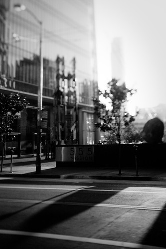
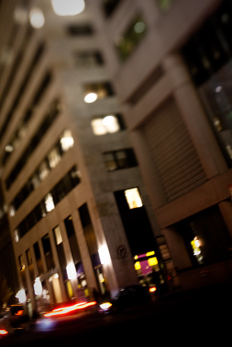
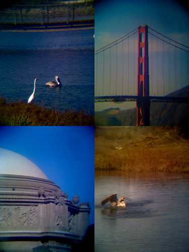
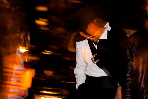
Star shaped bokeh from out-of-focus traffic downtown.
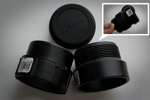
The basic idea of the kit is put a cutout shape in front of the camera lens, which shapes out-of-focus lights using the shape on the cutout [Optics nerd time: I'm not sure of the exact optics going on here, but what I'm guessing is that it masks the circle of confusion formed at the image plane with the cutout shape. Someone please correct me here if I'm wrong]. Udi took the idea of his DIY shaped bokeh and turned it into a product where you can swap in one of a number of pre-made cutouts.


What's in the box:

Bokeh Masters Kit Test: package contents

The masters kit comes with five pre-perforated sheets. Four of these contain the shaped cutouts, and the actual 'bokehtinator', which is used to mount the discs. Another sheet folds into a little box for storing the discs when they are not in use. A rubber-band is supplied so you can attach the bokehtinator to the camera itself.

When you first punch the discs out, you might get a feeling that the plastic is a bit on the flimsy side; in particular the folds bokehtinator seem like they might tear. However, after a two days of of testing I was pleasantly surprised to find that by just being mindful of not pulling along the fold lines it is indeed quite sturdy.


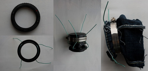
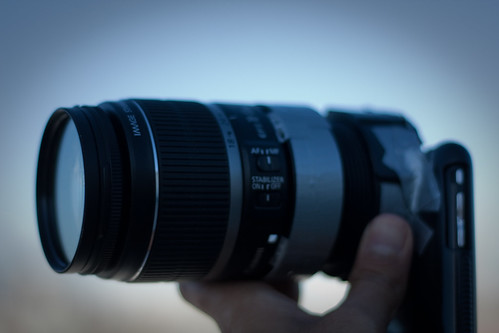
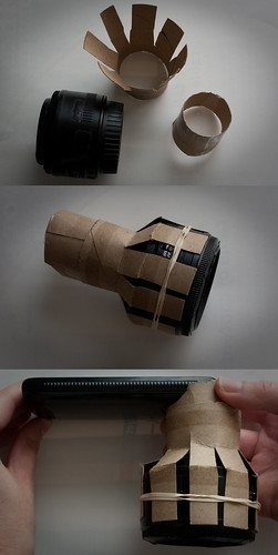
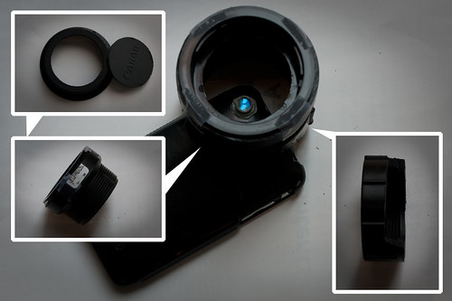
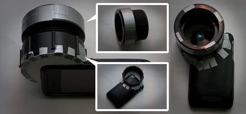
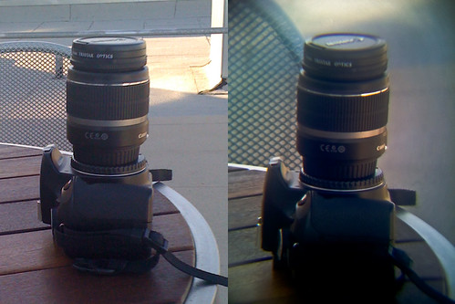
Attaching the bokehtinator is relatively simple - the tabs are folded around the lens and held in place with the rubber bands. A clever part of this design means that the focusing ring is still accessible for use, as opposed to the DIY cap-based designs which would prevent this. One thing that I quickly discovered was that I needed to attach the bokehtinator with a good 5mm gap away from the end of the lens to allow room for the focusing mechanism to work.


Learning to work with shaped bokeh:

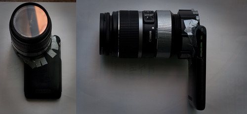
I used my trusty Canon 450D along with a f1.8 50mm nifty fifty. To really make use of the bokeh effects, you need out-of-focus light sources. If your lens has a good, big depth-of-field than you might be disappointed - as the instructions in the kit say, for this to work you need the aperture wide open (i.e. low f-stop).

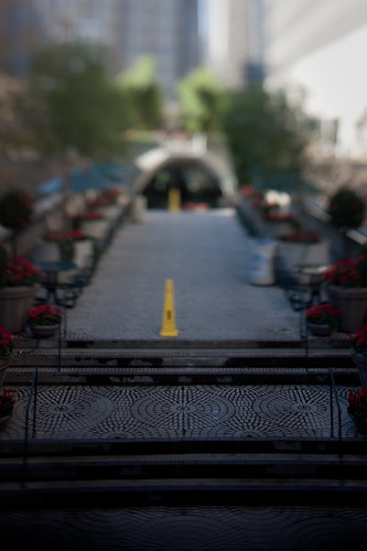
The sweet-spot for usage (as I understand it) is with portrait photography with a backdrop that has point light sources. As is sometimes the case for portrait photography, you need to get in close for it to work, or alternatively settle for blurring everything out to get the effect.

Bokeh Masters Kit Test: Building before and after
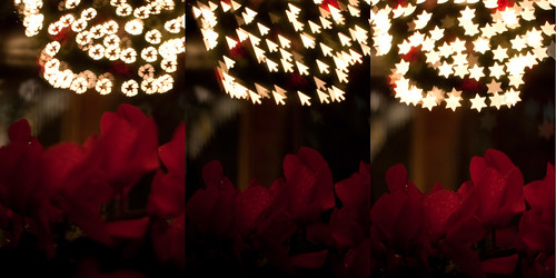
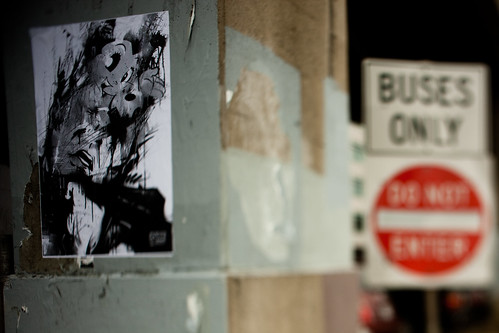
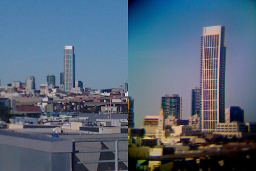
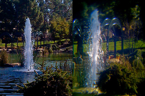
In focus with the bokehtinator, and out-of-focus (larger here)

In the shot above I've taken a photo of a building downtown. Unless I got really close to the building, it was going to be pretty unlikely that I was going to get only part of the building in focus (custom lenses aside). However, if you throw sharpness out of the window, you can still get an interesting looking shot.

Bokeh Masters Kit Test: Christmas tree before and after
Christmas tree: sharp and out-of-focus (larger here)

Bokeh Masters Kit Test: Racking focus
Christmas tree: racking focus (larger here)

By turning off autofocus and manually racking the focus back and forth, you can experiment with exactly how big you'd like the effect to be. In the example above, we start off with relatively small shaped bokeh, but a nice sharp foreground. As the focus is racked, we get bigger, more impressive looking bokeh but the foreground goes out of focus.


Comparing cutout discs:

Bokeh Masters Kit Test: Test discs and bokehtinator
Cutout discs tested: star, recycle, cursor

To see how it affected the technical aspects of shooting, I tested with three representative cutouts. I used the star, which provided a relatively simple shape and large aperture. The recycle symbol had a lot of detail and a smaller aperture, and the cursor symbol had and off-centre aperture.

The first thing that I found was that the multi-point autofocus no longer worked with the bokehtinator in place. This wasn't a big deal; I set the autofocus point to the centre of the image, which seemed to work fine for the star and the recycle, but wouldn't work at all for the cursor cutout.

I also got mixed results with metering. I prefer to use centre-weighted metering (in aperture priority mode) on my camera, which worked fine with the star and recycle discs, but tended to over-expose with the cursor.

Bokeh Masters Kit Test: Results with different discs #1
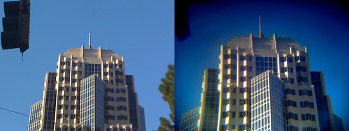
Top left: no disc, top right: recycle symbol, bottom left: cursor, bottom right: star

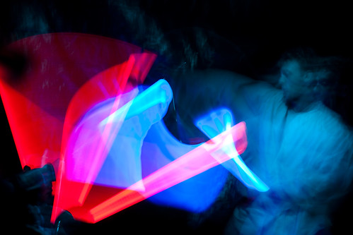
Once you get the camera set-up though, it's a bunch of fun. This is a great time of year to be playing around with this particular accessory as there are lots of seasonal decorations to give you point sources for your bokeh.

Bokeh Masters Kit Test: Results with different discs #2
Larger version here

The shaped bokeh is sharp - in particular, I do like how it turns otherwise plain-old background bokeh into sharp shapes, which (when the composition works) match a sharp foreground subject. I was also initially a bit doubtful about the sharpness of the cutouts when I first looked at the discs, but I'm happy to report that this wasn't a problem.


Impressions & conclusion:

One could easily argue that given the relatively simple nature of the kit, that you could build your own at home. If you're the kind of photographer that can do that, more power to you, but I'd say that then this isn't the kit for you. My feeling is that this kit is aimed at the photographer who just wants to get going with shaped bokeh and doesn't have the time or inclination to craft small cutouts.

It'd also make an awesome tool for portrait photographers who are looking to differentiate their work. As cheesy as it sounds, the provided good selection of cutouts means that you can quickly pick one out that suits the occasion.

In practice, I found that my shooting tended to consist of taking a few test shots on auto-metering and auto-focus, and then switching to both manual mode (for shutter speed) and manual focus. You also need to be mindful of the depth of field of the lens that you are using, and how a careful choice of both subject and distance from the camera will affect the result. As such, I don't think this kit is for the total beginner - however, I think an intermediate to advanced photographer would get a lot out of it.

If you fit into one of these categories, I'm going to go ahead and cheerfully recommend it.

13 December 2009

black and white

More fun with the plungercam mini - in black and white :)

pigeons on a mission redux
Pigeons on a mission (redux)

5 5 5
5 5 5

6 December 2009

Plungercam mini prototype

So last week I posted up a lengthy description of an experiment I did where I tried building an optical coupler for SLR lenses and camera phones. The post got reposted to a bunch of the major geek and regular news websites and about a zillion people dropped by to have a look.

A bunch of really interesting technical discussions and observations arose out of the whole thing, and for those folks involved (you know who you are) - you're awesome.

So, as demonstrated earlier, I'm a sucker for ugly camera mods. Following up on a discussion I had with the always brilliant fksr a few months ago, I wanted to prototype a revision on my plungercam design that properly allows for both tilt and shift whilst still being being able to be fixed in position for timelapse work.

Plungercam mini: prototype building

I had an old 28mm minolta lens lying about that seemed perfect for the job. It isn't a medium format lens, so the issue arose of getting it close enough to the camera sensor so we can do tilt and shift motions. In breaking with my principle of not disassembling lenses, I removed the f-stop adjustment mechanism at the back of the lens (above) so that the back end of it could comfortably fit inside the lens aperture on the camera.

Plungercam mini: prototype building

The next bit is the awesome part that fksr proposed. Instead of attaching the lens to the body by using a tube, use some sort of strut mechanism that allows the lens to be posed into position. By just using stiff wire, you can move the lens to almost anywhere you like.

I took a body cap and as per usual cut out the middle of it. I then added four small holes around the edge of the cap that wire could be threaded through. Using two lengths of wire, I added four struts. To test that it worked, I clamped the newly stripped-down lens to the struts using the classic metal plumbing clip. To keep light tight and to (mostly) protect it from the elements, I added a denim sleeve.

This new mechanism allows for both tilt and, significantly, shift movements. To adjust the lens, you just pull on the kinks on the wire until it is posed into the position you desire.

I haven't had a chance to systematically test the shift movements yet; the upcoming bad weather is going to be a bit of a damper on my plans to run about and do some shooting. However, I was able to do some casual shooting earlier on in the week with it.

leaning over

astro head

The two big advantages it seems to have so far: the control of focus is much more subtle, leading to the in-focus areas being much sharper than the original, and the wide field of view. Further testing and prototyping is in-progress :)

1 December 2009

The Phone-O-Scope: Attaching SLR lenses to an iPhone

[Edit #5: A slightly more sane hack: new DIY tilt-shift lens prototype]

[Edit #4: I've responded to some of the issues raised about image quality]

[Edit #3: Hi to all the folks from hackaday, wired, makezine, gizmodo, engadget, TUAW and all the other corners of the inter-tubes.]

[Edit #2: This post, translated into Russian and Chinese - how awesome is that!]

[Edit #1: See some of my other DIY projects (tilt-shift plungercam, papercraft etc) here]

[Edit #0: And follow me on twitter, here!]

I've been trying to learn a bit more about the optics involved in mid- to pro-level cameras, and I've been finding that getting out the tools and doing some hacking serves as a great mechanism for instruction. Just recently the idea of optical couplers - that is, a system to transmit light from one optical device to another to make an image - has gotten my attention.

Mainly just to see if it was possible (and to teach myself about optical couplers), I thought I'd try my hand at building an adapter so I could attach SLR lenses to my iPhone. The result is pretty cheesy, but nevertheless - I present to you, the Phone-O-Scope:

Phone-O-Scope: Completed build
The Phone-O-Scope with an 18-55mm lens attached.

Phone-O-Scope: In action
In use.

Just to get the inevitable question of 'why' out of the way - well, why not? As far as I can tell, I think this is the first - I couldn't find any similar SLR lens to camera phone attaching attempts anywhere else online (I'm not including the mini-lenses you can get as they're not 35mm lenses). The Phone-O-Scope doesn't take especially superb images, and it's a bit clumsy to handle. On the other hand, it's fun to shoot with and produces very analog (almost Holga-like) results. You also get the advantages of SLR lenses - that is, DOF effects, and the wide range of available focal lengths (i.e. macro to telephoto).

There are plenty of interesting designs for cameras floating about, and plenty of nice phones with reasonable optics attached. I'm hoping that this experiment takes the concept of a camera phone to it's illogical conclusion.

Construction

In keeping with my other optics experiments, I wanted to try something that required the minimum amount of dis assembly of expensive components (i.e. no warranty voiding!), as well as being cheap and relatively easy to assemble. The parts list (roughly) is:

  • Camera phone (in this case, an iPhone)
  • SLR lens (in this case, two Canon EF lenses)
  • Old surplus canon lens end cap
  • Hard phone case (cheapie iPhone case, ~US$10)
  • Old optical mechanism from a CD or DVD player (scrap - cost me $0)
  • Bit of old sticky putty (again, $0)
  • Cardboard tube for testing
  • 2-inch PVC pipe couplers (about US$3 each)
  • Duct tape
I already had the lenses and phone, so the project cost me less than US$10.

Step 1:

Phone-O-Scope: Step 1

Get the case off the phone first. This particular design doesn't do anything destructive to the phone or the case, but it's a good idea not to tempt fate :)

Step 2:

Phone-O-Scope: Step 2

You'll need to take laser pickup (see left inset, above) out of the CD player and start to pull it to bits. I was able to get three lenses out; you'll need to verify that each one is a magnifier. These can be stacked to achieve more magnification of the lens aperture (when it is attached); the more you can magnify, the less vignetted the image will be.

I wrapped a thin layer of putty around the edges of the stacked lenses to stick thin strips of paper around the edges of the lenses. This is so that they can be assembled together and handled as a single unit.

Step 3:

Phone-O-Scope: Step 3

Take the lens stack and insert it into the cameraphone case; I again used a bit of putty to hold it into place. Just out of interest - this turns the cameraphone into a pretty decent microscope. The depth of field is rubbish (in my case, about 1-2mm) but the magnification is huge.

Step 4:

Phone-O-Scope: Step 4

Now that you've got the magnifier lenses in place, I'd recommend building a simple test rig to check roughly the distance you will need between the camera and the back of the SLR lens. The proper thing to do is do some proper calculations involving the measured actual magnification of the lens stack and the flange focal distance of the SLR lens. However, if you lack the equipment for proper measurement, you can estimate by building a set of sliding tubes with an SLR lens attached.

Start off by taking two sections of tubing, one slightly narrower than the other so it can slide inside the other. Cut strips along the tube with wider diameter so you can hold the lens on it using a rubber band. Attach this whole mechanism over the camera phone and magnifier.

The tricky part now is to get this working mechanism to make a picture. You'll need to slide the outer tube back and forth as well as adjusting the focusing ring on the lens, and there'll be a lot of experimentation until you get a sharp picture. If you find that all your images are heavily vignetted, you'll need to add another lens to the magnifier stack.

Step 5:

Phone-O-Scope: Step 5

Components for the actual adapter. I used an old end lens cap, and two pieces of two-inch PVC pipe connectors. It was important that the connectors could be connected via a screw thread - this way we can move the whole SLR lens back and forth for secondary focusing.

Step 6:

Phone-O-Scope: Step 6

Cut a hole in the lens end cap (inset top left). Use the measurements for the top and bottom cardboard tubes (step 4) to figure out how much you'll need to trim the PVC connectors. The distance that you get from the cardboard tubes should be the same as when the PVC connectors are roughly screwed together halfway, so you get lots of room to move them back and forth. To the top connector, attach the end cap. If you need, cut a notch out of the bottom connector (inset, bottom right) so it fits nicely on the case. Attach the SLR lens just and verify that your measurements are right.

Step 7:

Phone-O-Scope: Step 7

Duct tape madness. Attach the bottom connector to the camera phone case (inset, middle bottom) using thin strips of duct tape. Make sure you get a nice tight fit, but don't go overboard with the tape. Use a bit more tape to also firmly attach the lens cap to the top PVC connector (inset, middle top). Don't forget to attach a bit of cardboard at the back to prevent too much light leakage into the mechanism. Screw the top connector to the bottom, and the Phone-O-Scope is complete (right).

50mm lens attached to the Phone-O-Scope:

Phone-O-Scope: 50mm attached


18-55mm lens attached to the Phone-O-Scope:

Phone-O-Scope: 18-55mm attached


Image quality

As I'd mentioned earlier, the point of this mod is to learn what is needed to successfully build an optical coupler. One important thing to keep in mind is that even if it doesn't work perfectly, it's still a win - I've observed what doesn't work and I'll have a much better idea about how to do it better next time.

The image quality issues come down to two main factors:

1) Optical axis alignment. The phone, lens stack and SLR lens alignment isn't good enough yet. I've found that small alignment errors in the axis - even as little as one or two millimeters - is enough to cause significant portions of the image to become out of focus

2) Image stack lenses used. The lenses are out of a CD player; they're not perfect magnifiers, and, they're designed to work with a specific wavelength of light. This is a significant contributor to the chromatic aberration observed.

Technical issues aside, I'd also say that there is something to be said for having an unpredictable mechanism that prevents you from getting the same photo twice. I've taken a lot of photos with the plungercam, and I've found that although I do take a lot of images that are no good, there are a few that are pretty awesome. And the best bit about that is that I can say with reasonable certainty that it'll be impossible to ever get those same shots ever again. If that doesn't appeal to you, then this type of modification is not for you.

Results

Phone-O-Scope: montage

The Phone-O-Scope produces fuzzy, Holga-like images. I think a lot of the image artifacts (strong chromatic aberration, bizarro lens distortion) are down to the extreme magnifier stack. However, I've tested it with a few Canon EF lenses now and it does seem to work reasonably well with every one. At the very least, it seems to work like a telescope for the iPhone, and it is fun to shoot with (not to mention the odd looks I get when I'm using it :)

I've got a series of comparison images below; an iPhone picture is on the left, and a Phone-O-Scope image is on the right. In the interest of transparency: I've made some small corrections to the Phone-O-Scope images (exposure, white & black points):

Phone-O-Scope: SOMA image comparison
Note the odd barrel distortion and vignetting in the Phone-O-Scope image. Taken with the 18-55mm lens.


Phone-O-Scope: Closeup image comparison
The Phone-O-Scope isn't quite as sharp, but you can clearly see how the camera now has a definite DOF effect - in the standard iPhone picture, nearly everything is in focus. Taken with the 50mm lens.


Phone-O-Scope: Distant image comparison
Taken with the 50mm lens.

Phone-O-Scope: Outdoor scene comparison
Taken with the 50mm lens.


25 November 2009

empty spaces

A while ago I saw a collection of photos of Hong Kong where the photographer had taken photos of the city in such a way that it did indeed look not only deserted, but abandoned. His technique was simple, but rewarding - he just used a telephoto lens, picked a spot and just waited and waited until everyone cleared off from the desired shot, sort of like inverse bird-watching. I wish I could remember where I saw the photos, as it was a really great set.


It's not an unexplored theme though - this gentleman took photos of an oddly abandoned looking London by scooting around on a bike on Christmas morning. There's a whole group on flickr that I've just discovered devoted to the topic of normal towns looking like ghost towns.

empty spaces: spin me round


One bloke who has done well out of the idea is Christopher Thomas. His formula was to get around New York in the predawn light with a larger format camera and he gets eerie, luminous images of New York (book link here).

empty spaces: sneaking away

1 November 2009

Caliber SF Halloween Photowalk

The excellent folks at caliber SF organised a Halloween photowalk across SF yesterday; it was a riot.

Rumnose :)

social climber

halloween wars

disco hat

Full set here, even more from the other photogs here :)

11 September 2009

Why I ride a bike

Route 1: Getting the 22 MUNI bus back home from work


Distance: 6.7km
Time: 45 mins (not including time to walk to the bus stop!)
Average speed: 9km/h (!!)
Pros: Not driving, can read a book
Cons: Getting stabbed in the pancreas, the malefic odour of a San Francisco transient as they sit right next to you

Route 2: Riding my bike


Distance: 11.0km
Time: 37 minutes
Average speed: 18 km/h
Pros: Exercise, the view along the waterfront, not being tied to a bus schedule
Cons: Headphone-wearing pedestrians walking out in front of you, splashback from the giant octopus that occasionally tries to destroy the Golden Gate Bridge

7 September 2009

Bay Bridge Bypass

[Prefix: A huge, enormous thanks has to go out to Margena Wade, (Community Liaison Officer) and other staff at the Bay Bridge project at Caltrans for giving me the opportunity to go out and look at the construction of the bridge. It's an amazing project on an enormous scale, and I've been enormously lucky to have had the opportunity to go out and have a look at it first hand :)]

I set out on Friday afternoon after work to have a look at the Bay Bridge bypass construction work first hand. Heading over on the trusty 108 MUNI, I scuttled about Yerba Buena and Treasure Island trying to get a few good shots. I nabbed a spectacular moonrise over the construction site:

Bay Bridge bypass: Moonrise behind Bay Bridge

...as well as a time-lapse with ye olde plungercam of the old bridge section being rolled out, as well as a timelapse of the moonrise :)


However, I was lucky enough to be invited back to the island for a tour of the site on Saturday evening - and it was absolutely spectacular.

Bay bridge bypass: construction site


This is the boat pier on the East side of the bay bridge construction site. Here a service connected the two Caltrans command centres at Yerba Buena island, and it's from here I got the awesome ferry ride out on the water to have a look at the entire span of the bridge.

On the left hand side of the image you can see the new section of the bridge completely rolled into place; when I arrived on Saturday evening it was being worked on by engineering crews who were working on a pile of verification and connection tasks.

The bypass weighs about 7000 tons (!) and was assembled 50m up in the air and slid into place on rails. I asked about what it takes to overcome that sort of inertia to get it moving, and the answer was lots of hydraulics and dish soap.

In the mid-ground on the right two-thirds of the image, you can see the existing Bay bridge; just behind it is the new bridge. For the majority of the distance, the deck is in a side-by side configuration. I believe that the current point where it is up to is named W2; from there until pier E2 (mostly obscured by the construction work) it becomes a deck suspended by a pylon, and after that it converts into a double deck configuration to enter into Yerba Buena island.

Bay bridge bypass: E2 and W2


On the far left of the image, you can see 'falsework' construction leading up to pier E2; on the right, you can see the twin deck coming over from Oakland and pier W2. The falsework is in place so that the deck, which is normally going to be suspended from a pylon, can be constructed whilst the pylon is put into place. When the suspension cables are added, the falsework will be removed.

Bay bridge bypass: The Left Coast Lifter


The Left Coast Lifter is one of the world's largest floating cranes, and was constructed specifically for the job of installing sections of the Bay Bridge. This behemoth is about 30 stories high (!) and after the job with the Bay Bridge is likely to be deployed elsewhere. Before construction it was used to lift a sunken WW II tugboat. Here you can see it parked at Oakland, just in front of some falsework that is going to be used to temporarily support the span of the new bridge.

Bay bridge bypass: Plungercammed Oakland crane


One of the many characteristic cranes lining the Oakland foreshore.

Bay bridge bypass: Work on the cracked eyebar on the east span of the Bay Bridge


Inspection of the Bay Bridge revealed that a two-inch crack in an eyebar on the East span of the bridge; I'm pretty sure the crane and lift in the middle are near where the broken eyebar is. The crack means that the re-opening of the bridge may need to be delayed whist crews work overnight on fixing the problem.

Bay bridge bypass: East span of the Bay bridge with repair work on the broken eyebar


This is my favourite shot; the plungercam does all sorts of interesting things with smearing out point light sources. Golden hour at sunset is very, very kind to photographers in the Bay area summer :)

In the centre of the image you just make out the crane next to the newly discovered broken eyebar support on the bridge.

All in all, it was an awesome weekend :D The full photoset is here.